
Identify the Cause — Minimize the Cost - Part 1 of 3
This particular topic is one of the most common problems that continue to plague the flexographer on an on-going basis. It was even hard for me to come up with a simple title because the distinction between bounce, gear-marks and banding is often very blurred. How we choose to label this common defect often leads to a misdiagnosis. Even more frustrating, after the "proper identification", the problem seems to be a moving target; here today, gone tomorrow and back yet again. Trying to predict these defects can be like playing a shell game where you try to keep track of which shell has the pea, only to feel at times that you ARE the pea.
When I was young one of the things that really irritated me was to get 55 minutes into a television show only to realize that I would have to tune in next week for the conclusion, so I want to be upfront about this article being a multi-part series. The possible causes of these defects and corresponding options for resolution are many and thus will be covered over three parts. With each article you will hopefully gather more information to help you correctly identify, measure and diagnose - and finally take action - to minimize or altogether eliminate the print defect. In some cases the solution may be a design or procedure change, while other root causes can be addressed with product or consumable changes, and finally, some requiring mechanical or tooling changes.
Locating these defects is very basic and can be executed by using your most valuable tool, the human eye. Screens and vignettes can be used to identify defects that result in light and dark areas, or bands that stretch across the entire web/sheet width. Common names for these print defects include barring, banding, gear-marks, and gear chatter. These defects are often attributed to gear problems, poor design layout or doctor blade chatter. While these diagnoses are indeed often a root cause, there can also be localized problems in platemaking, consumable materials, press components or even in the design elements themselves.
In order to move forward through this diagnosis we must first determine what is the correct I.D. of the print defect. Is the defect bounce, gear-marks/chatter or barring/banding? Later in the article we will go into greater depth regarding each of these items. At this point in the process we are just looking to identify the defect by using basic tools and observations. Let's start by defining some of the differences in these issues.
Barring or banding appears as light and dark bars in solids and particularly in the screens and vignettes. It spans across the web, perpendicular to the web direction. Barring/banding can also be a result of improper pitch setting or gear wear, but typically does not have a correlation to the spacing of teeth, but rather bouncing that occurs from mechanical wear or balance. In some cases, the defect will fall within the same area repeating with each rotation of the impression cylinder. The most common diagnosis of banding is attributed to the ink delivery system, including pumping and doctor blade issues. Bounce will often appear as a void of ink across the web width where the plate and impression cylinder temporarily lose contact. The root cause of bounce is most often attributed to cylinder balance and/or design layout.
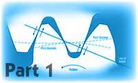
Gear marks and chatter typically have a repeat pattern that aligns with the drive gear of the print cylinder or servo motor. If it is a 10 dp (diametral pitch) gear, then the light and dark areas will repeat every .31416" (1/10 of Π). If the gear is 1/4 cp (circumferential pitch), the light and dark areas repeat every 1/4", and so on. In the case of improper pitch setting you may hear gear hum or chatter. You may also see sharpening of the gear teeth on the print cylinder drive gear. The pattern across the web will most likely repeat with the same frequency as the gear teeth. A very common mis-conception is that gear-marks cannot exist if a servo driven press is being used. This is not at all the case. While you may not know the gear pitch of the internal gears of your servo drive motors, you will see a distinct repeating pattern that will remain consistent in the distance between the light and darks areas.
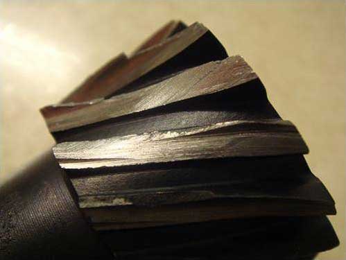
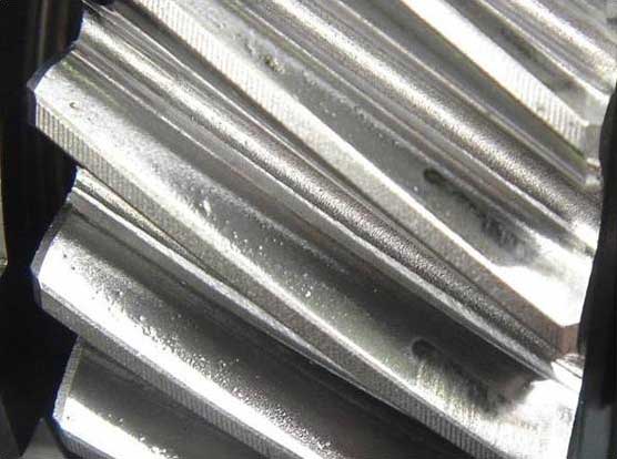
Because gear-marks, chatter, and gear related defects are among the most easily identified, we will begin here. Gears require a small amount of space between gear teeth as they come together to allow them to mesh correctly with sufficient lubrication. Gear teeth should be examined, cleaned and lubricated regularly. Wear often shows up as the top of the gear begins sharpening. As this wear or sharpening occurs, it affects the amount of space between the gear teeth. Backlash (also called gear slop) is a condition in which the space between the gear teeth increases. This is usually caused by insufficient meshing or gear wear. Backlash creates vibration and increases plate bounce, and typically shows up most visibly in vignettes and screens.
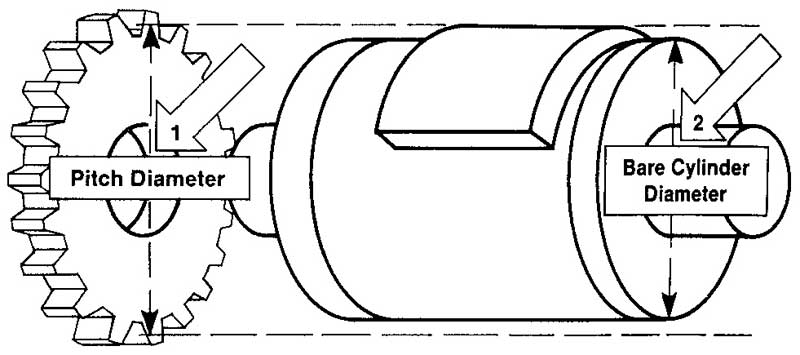
The impression drum/cylinder, plate cylinder, and anilox must rotate at exactly the same speed that the web is traveling. If one gear is set/meshed past the pitch diameter it will cause the roll to rotate at a slower speed than desired. In this case the press operator may hear gear humming. If one gear is set/meshed before the pitch diameter the roll it drives will rotate at a faster speed than desired. The CFD (complete finished diameter) of the print cylinder must match perfectly with the diameter of the gear used to propel them (non-servo). Mismatched roll diameters (pitch) create a mismatch in speed, which translates to vibration, resulting in uneven/over impression. This appears as slurred dots, barring/banding, gear marks and plate wear on the print sample.
Gearless chatter can occur whether the press is direct drive or if the print cylinders are driven by servo motors. Servo motors can replicate gear chatter when bearing wear and/or inner gear wear is present. You may not see them, but they are there.
Upcoming topics will include the following.
- Press Mechanics
- Balance and Deflection
- Measuring Vibration and Tools
- Design and Doctor Blades
- Solutions and Band Aids
We have formed our Technical Solutions Group to encompass our full range of expertise in all critical areas of the flexo process. This team is made up of industry professionals dedicated to staying up to date on new technologies, armed with the latest in diagnostic tools, and experienced in problem solving that can achieve sustainable results. This team has walked in your shoes and has felt your pain. For any specific questions please feel free to contact me at 847-922-0134 or treece@teamflexo.com.
You can read the entire 3-part series here:
Bounce, Gear-marks, & Banding - Identify the Cause — Minimize the Cost - Part 1
Bounce, Gear-marks, & Banding - Identify the Cause — Minimize the Cost - Part 2
Bounce, Gear-marks, & Banding - Identify the Cause — Minimize the Cost - Part 3
- Tim Reece, APR Tech Services Group