
Identify the Cause — Minimize the Cost - Part 3 of 3
The Conclusion
In Part 1 of this series, the focus was on correctly defining and identifying print defects. Part 2 dealt with how the actions of support groups and reactions of the press operator can sometimes minimize the effect while other times they are the root cause of the effect. Part 3 is "the Conclusion" of this series, with the focus being on measuring devices used to locate these root causes, and how to use these tools and skills to quickly identify, isolate, and perform corrective action to minimize or eliminate the defect.
Getting Accurate Metrics of the Problem
Once the defect has been accurately identified, the next step is to control the defect. In order to effectively control the defect, we must have an accurate means of measurement. Often the tools to do this can exceed the limitations of our dial indicators and even our two most powerful tools, our eyes and ears. Most of these devices are used on press to identify causes of bounce, gear-marks, and banding in order to avoid generating printed scrap. These tools include the following items:
- Horizontal dynamic balancing systems
- Mechanical and electronic stethoscopes
- Vibration data collectors
- Hand-held stroboscopes
- Image analysis devices
Horizontal Dynamic Balancing Systems
Horizontal dynamic balancing systems certainly are important in the manufacturing of many of our press components like print cylinders, anilox bases, and impression rollers. However, these devices really are not a practical solution to field balancing. These units cost approximately $25,000 for most narrow web applications and wide web devices can exceed well over $50,000. Therefore it is best to leave the dynamic balancing to the manufacturers and request a report of dynamic balancing upon the initial purchase and any repair or replacement to the base or journals.
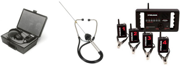
Mechanical and Electronic Stethoscopes
Mechanical and electronic stethoscopes are some of the easiest tools to use. These devices do an excellent job in finding the precise location of emitted vibration and level of vibration stemming from misalignment, T.I.R., imbalance, wear, and improper pitch or pressure angles of gear teeth within the print deck or gear train. Mechanical stethoscopes are easy to use for very basic locating of audible indicators and are very inexpensive. However, vibration often travels from one component through the next; therefore being able to isolate print stations or individual components carries a distinct advantage. Electronic stethoscopes allow the operator to monitor several areas of interest, in this case, print stations or components within the print station. Headphones shut out surrounding sound, while color-coded super sensitive microphone clamps attach to problem areas. The main control switch isolates each channel and amplifies it to the user, allowing the operator an instant cross-comparison between all channels. By using both an electronic stethoscope and a vibration data collector, the user can quickly determine the weak link in the print station.
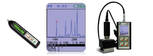
Vibration Data Collectors
Vibration Data Collectors are used for monitoring and analysis of cylinder and roller conditions. Monitoring of bearing and bushing condition is based on high frequency enveloping, often recording as many as 500 data points per measurement. A PC connection, via USB, is generally required for detailed analysis. When using these devices within a print station, an external sensor with a magnetic holder enables you to collect broadband data accurately and reliably. Some vibration data collectors are paired with a stroboscope connection to estimate shaft speed and phase of the fundamental frequency. This feature allows the operator to perform a speed match analysis between components within the print station and identify pitch issues.
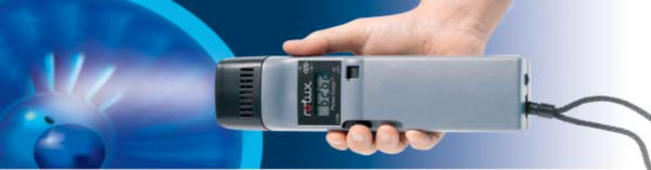
Hand-Held Stroboscopes
Hand-held stroboscopes measure and test rotational and vibrational movements, making them an ideal low-cost instrument to have press-side. When the displayed strobe frequency equals the true speed, the moving part will appear stationary. The stroboscope can measure and detect drift and undesired harmonic resonance in devices and machine parts or unbalanced conditions. The device determines the speed of rotation or frequency of oscillation when it is not possible to interfere with a production run, which is often the case. Stroboscopes can also reach into difficult to access places or areas with especially sensitive systems.
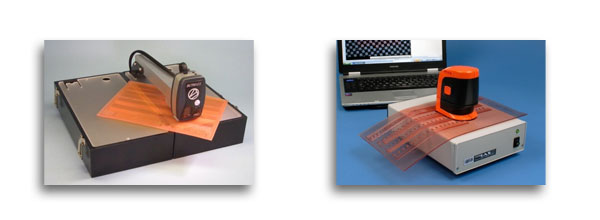
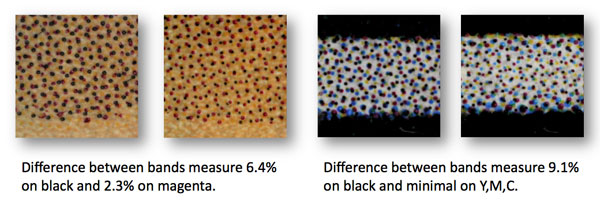
Image Analysis Systems
Image Analysis Systems are tools used to identify root causes of printed defects after the substrate is printed. Devices like the Flexo-IASII and the BetaPro go far beyond measuring typical dot gain. Image analysis equipment can identify just how much the dots are varying between the bands or gear-marks within screened areas. They will also measure the amount of slur within screens. Slur is the elongation of dots. When a round dot is slurred it becomes more oval-shaped. Typically this lengthening of the dot occurs in the web direction. This generally alerts the operator to one of a couple of different areas of concern. Most commonly slur is a result of too much plate relief. In other words, the distance from the plate face to the floor is too great leaving the dots un-supported and likely to lean under impression, resulting in elongated dots. However, it can also indicate a speed match problem between anilox, plate cylinder, and/or impression roll and plays into contributing factors of bounce, gear-marks, and banding. The unit of measurement for slur is Box Ratio. Box Ratio is the ratio of the vertical dimension to the horizontal dimension of the minimum rectangular bounding box that can be fit around the individual dots (Box Ratio = maxH/maxW). In other words, this is the maximum vertical height of the dot divided by the maximum horizontal width of the dot. If no slur is present the Box Ratio would have a value of 1.00. This means the height and width are identical. What most people prefer to know is what is considered a passing versus a failing box ratio. A value of .90 — 1.10 would generally be passing and you would not notice slur through a loupe.
Fix the Defects or Fix The Outcome?
So here we are... we may now understand how to identify these defects and, through proper analysis and measurement using the right tools, even identify their root cause, but the problem has not been resolved. Once these defects surface chances are the press is sitting idle and waiting on us to make a decision about what must be done. From here we have a couple of different paths we may take. In order to decide how to proceed, we must choose based on the defect whether we try to "absorb" the defect or fix the root cause. Using the proper tools to measure press components, the root cause of the defect can be identified; the course of action may then vary. Worn components in some cases can be repaired or re-built, but often must be replaced, but that doesn't necessarily help you today.
Calling some solutions Band-Aids, really is not fair. The fact is, sometimes absorbing the defect is the best solution. Here is an example: Although dynamic balancing may indeed be the long-term answer to a particular roller or cylinder, field balancing our cylinders and rollers really is not a viable "immediate" option. Therefore absorbing the defect or vibration may be the immediate and possibly long-term answer. Here is another example: I've heard countless times individuals blame bounce, gear-marks, and banding on the mounting tape (stickyback). I honestly do not know of any stickyback that creates any of these print defects. However, there are some that do a much better job of absorbing these defects than others.
Smoothing Out the Rough Spots
The way I see it, stickyback is to printing as shocks or struts are to our vehicles. It isn't that our vehicles are shaking and vibrating on their own, and therefore we need shocks to be comfortable. We need shocks for the inconsistencies of the road. We need them to absorb the surface we are traveling, whether it is across RR tracks or dodging potholes in Ohio. Often a softer stickyback with excellent resilience properties can hide the effects of worn components and vibration. A couple of closed-cell examples are Lohmann's 4.1/5.1 and 3M's 1115/1120.
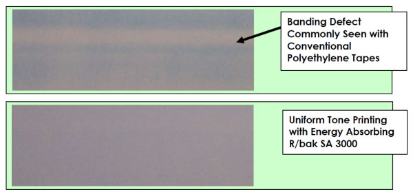
Other tape products that specialize in addressing bounce, gear-marks, and banding include Rogers R/bak SA3000 and ChannalBAC. Rogers R/bak open-cell urethane cushion mounting tape is designed to reduce gear banding and press bounce by dissipating vibration resulting in a more uniform tonal patch or screen.
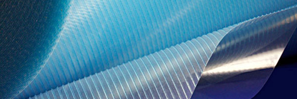
ChannalBAC™ Displacement Technology Mounting Material completely separates its air and elastomeric components by forming solid elastomeric channels separated by channels of air within its membrane. The result is a cushion that disperses uneven impression and surface area. This technology is ideal for problematic graphic design layouts.
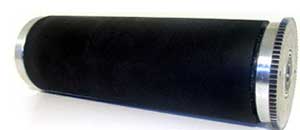
Manufacturers of stickyback are not the only suppliers focusing on reducing these print defects. Moving the responsibility from the stickyback to the cylinder is a technology developed specifically for narrow web printers. Nu Tech Coatings Performance Enhancing Cylinder (PEC) offers a special surface coating that greatly reduces and often eliminates banding and gear-marks. The unique coating is applied directly on to your existing or newly manufactured cylinder. With this technology the plates are mounted directly to the cylinder with a .005" tape, eliminating the 15 or 20 mil stickyback. The surface is reported to be compatible with all flexo solvents and inks.
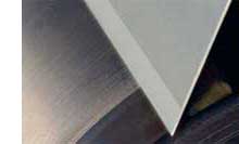
Daetwyler's Stable Flex doctor blade is focused on eliminating doctor blade chatter. It has a long and flexible lamella (thin layer membrane) with a highly polished edge. This tip configuration allows the blade to absorb the vibrations by allowing deflection to compensate for the vibration or the bounce of the anilox roll when running at higher speeds. Doctor blade chatter marks are virtually eliminated and the ink film is transferred smoothly from the Anilox roller to the printing plate.
What Have We Learned?
The key points that you should take away from this series are:
- There are many potential causes for these print defect issues.
- There are a number of devices and technologies available to help identify or target the root causes.
- Once the root cause is identified, there are many possible ways to lessen or remove the issues causing the problem.
In the end though, I hope you can see the importance of partnering with a vendor that can recommend the right tools and products that you can use to bring your problems to an affordable, timely and (reasonably) successful resolution, be that through some absorption of a vibration, or a true mechanical fix.
APR Technical Solutions Group
We have formed our Technical Solutions Group to encompass our full range of expertise in all critical areas of the flexo process. This team is made up of industry professionals dedicated to being up to date on new technologies, armed with the latest in diagnostic tools, and experienced in problem solving that can achieve sustainable results. The TSG have walked in your shoes, and has felt your pain. For any specific questions please feel free to contact me at 847-922-0134 or [email protected].
You can read the entire 3-part series here:
Bounce, Gear-marks, & Banding - Identify the Cause — Minimize the Cost - Part 1
Bounce, Gear-marks, & Banding - Identify the Cause — Minimize the Cost - Part 2
Bounce, Gear-marks, & Banding - Identify the Cause — Minimize the Cost - Part 3
- Tim Reece, APR Tech Services Group